|
GD-Itronix DynaVue Display Technology
The
Ultimate Outdoor-Readable Touch-Screen Display
(June
4, 2007)
by
Technology Editor Geoff Walker -- view PDF version
Don't you
just hate it when some marketing guy labels something as "ultimate"?
Well, I've found something that really should be labeled as "ultimate."
It's General Dynamics (GD) Itronix' brand-new DynaVueTM
outdoor-readable touch-screen display technology. The American Heritage Dictionary
defines "ultimate" as "representing or exhibiting the greatest
possible development or sophistication," and that's an appropriate
description of this new technology. I've been studying and writing about outdoor-readable
screens for quite a while, and there simply isn't anything more that can be
done to a touch-screen-equipped transmissive LCD to make it work any better
outdoors.
Defining
the Problem
To support
my declaration of superiority, this article explains what GD-Itronix has done
and how it works. But before that, to set the stage and describe the scenery,
this article defines the problem, explains how to quantify outdoor readability
and discusses three alternatives for improving outdoor readability.
The real
problem in making any display readable outdoors is reflections. If the light
reflected by the surface of the display is close to or greater than the amount
of light emitted by the display, it can't be read.* In order to read something
on a display, there must be a visible difference between the whitest and blackest
parts of an image on the display. If the surface of the display is reflecting
a lot of light, the difference in the light emitted by the whitest and blackest
parts of the screen is masked ("washed out"), and whatever is on
the screen can't be seen.
The difference
between the whitest white and the blackest black on a display is called the
contrast ratio. The "intrinsic" (datasheet) contrast ratio of a
typical LCD panel is usually at least several hundred to one, and it can be
as high as 1,000:1. In simplified form, intrinsic contrast ratio is calculated
as the amount of light emitted by the brightest white pixel divided by the
amount of light emitted by the darkest black pixel, with the measurement being
made in a dark room. Since an LCD's backlight is always on, what's really
being measured is the ability of the black pixel to block the transmission
of the backlight. It should be fairly obvious that intrinsic contrast ratio
has little or nothing to do with outdoor readability.
Real-World
Contrast Ratio
In the real
world, a user looks at the whole screen outdoors, not just at one pixel in
a dark room. Accordingly, an entirely different method of measuring the contrast
ratio is used in bright-light environments. There isn't a standard term for
this "real world" contrast ratio; it's variously called "high
ambient", "extrinsic" or "effective" contrast ratio.
For the remainder of this article it will be called the latter. Unfortunately,
effective contrast ratio (ECR) numbers are rarely published because they depend
on many hard-to-control factors. As a result, it's usually necessary to estimate
the ECR for any particular display by plugging the display's reflectivity
and backlight brightness into a rule-of-thumb formula. The formula is as follows:
ECR
= 1 + (Emitted_Light / Reflected_Light)
In this
formula, "Emitted_Light" is usually the manufacturer's specification
for the brightness of the backlight in nits. ("Nits" is display-industry
slang for "candela per meter squared", or cd/m2, which
is a technical measure of light intensity.) "Reflected_Light" is
the amount of light reflected by the surface of the display. This is calculated
by multiplying the ambient light in nits by the percentage reflectivity of
the display. Ambient light is normally measured in lux. Sunlight ranges from
approximately 30,000 lux to 100,000 lux; to convert lux to nits, the value
must be divided by Pi (3.14159). The low end of the ambient sunlight range
is therefore usually specified as 10,000 nits (rounding up from 9,549).
Effective
contrast ratio numbers for LCDs are typically in the range of 1:1 to 20:1.
While there is no hard and firm standard, the following table provides a generally
accepted interpretation of ECR values.
|
Effective Contrast
Ratio (ECR) |
LCD
Outdoor Readability
|
| 1-2 |
Unreadable
in sunlight |
| 3-4 |
Adequately
readable in shade; barely readable in sunlight |
| 5-9 |
Adequately
readable in sunlight; looks OK |
| 10 |
Very
readable in sunlight; looks good |
| 15 |
Outstanding
readability; looks great |
| 20 |
Totally
awesome; excellent readability; can't be improved |
For comparison,
the equivalent ECR of the New York Times newspaper in sunlight is around 20:1,
which is about as good as it gets. A typical notebook LCD in 2007 has a 200-nit
backlight and a surface reflectivity of about 2%. Plugging these numbers into
the ECR formula shows that the typical notebook is essentially unreadable
in sunlight, as follows:
ECR
= 1 + (200 / (10,000 x 0.02)) = 1 + (200 / 200) = 2:1
High-Brightness
Backlights
Since the
backlight brightness appears in the ECR formula, it seems reasonable that
increasing the backlight brightness should make the display more readable
outdoors. Typical "high-bright" displays used in industrial applications
have 1,000-nit backlights. Substituting 1,000 for 200 in the numerator of
the formula yields an ECR of 6:1, which is "adequately readable in sunlight".
However,
there are several problems with this approach. First, increasing the backlight
brightness to 1,000 nits isn't appropriate for portable computers. It drastically
increases the power consumption, which reduces battery life and generates
a lot of heat which must be removed with a fan or heatsink. Second, the extra
brightness tends to overpower the dark pixels' ability to block light, which
causes dark colors to appear gray and the image to look washed out. Third,
this approach assumes that the reflectivity of the display surface remains
at 2%, which is usually not the case for any display with a protective cover
or touch screen.
Resistive
Touch Screens
Figure 1 below shows the construction of a typical analog-resistive
touch screen. This type of touch screen is very commonly used in portable
computers. (Note: Numbers in parentheses in the following paragraphs refer
to the layer ID numbers on the right side of each Figure.)
A resistive touch screen consists of solid glass substrate (6) coated with
indium tin oxide (ITO) (3), a transparent conductor. A flexible polyester
(PET) membrane (2) also coated with ITO (3) is suspended above the glass substrate.
Transparent spacer dots (5) keep the two conductive surfaces apart, forming
an air gap (4). A hardcoat (1) makes the surface of the polyester membrane
more resistant to wear. The force of a touch collapses the membrane, causing
contact between the conductive surfaces. Electronics measures the resistance
along the edges in two dimensions and calculates the point of touch.
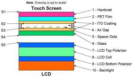
Figure 1: Construction of a typical
analog-resistive touch screen
Because
of the air gaps, a resistive touch screen has four reflecting surfaces, identified
as S1 through S4 in Figure 1 above. In addition, the LCD surface also reflects
light (S5 in Figure 1). Surfaces S1 and S4 each reflect 4% of the incident
light (normal for PET and glass), while surfaces S2 and S3 each reflect around
5% (higher because of the ITO). Surface S5 reflects about 2%, as previously
described. The total reflectivity is therefore 20%. Plugging 20% into the
ECR formula with a 1,000 nit backlight yields the following result:
ECR
= 1 + (1,000 / (10,000 x 0.20)) = 1 + (1,000 / 2,000) = 1.5
It's clear
that an LCD with an untreated resistive touch screen is unreadable in sunlight,
even with a 1,000-nit backlight!
Resistive
Touch Screen Treatment #1
There are
two alternative treatments that can be applied to resistive touch screens
to reduce their reflectivity. In the first treatment, touch-screen surfaces
S1 through S4 and the LCD surface S5 in Figure 1 are coated with anti-reflective
(AR) material.
AR coatings
are sometimes called "index-matching films" because one of their
functions is to reduce the effect of the difference in index of refraction
between air (1.0) and glass (1.5), PET (1.6) or ITO (2.0). Yet another name
for AR coatings is "quarter-wavelength films." If the thickness
of an AR coating is exactly one-quarter (or an odd multiple of one quarter)
of the wavelength of light, destructive optical interference takes place and
some of the reflections cancel each other out. High-quality AR coatings consist
of multiple layers of different materials, and they're not inexpensive, so
this treatment can multiply the cost of the touch screen by as much as 3X
or 4X.
The best
performance that can be achieved with five AR coatings is a total reflectivity
of around 5% (S1 through S5 = 0.5% + 2.5% + 1% + 0.5% + 0.5%). The primary
constraint is that reducing reflections from ITO on PET film (surface S2)
is particularly difficult because the required flexibility limits the number
of AR material layers that can be applied. While the resulting 5% is a substantial
improvement over the 20% described above for a totally untreated touch screen
& LCD, it's still not good enough, since even with a 500-nit backlight,
the ECR is still only 2:1.
Resistive
Touch Screen Treatment #2
The second
alternative treatment involves the use of a circular polarizer. This requires
a bit of background explanation before proceeding further. Figure 2 below
illustrates how a circular polarizer eliminates reflections.
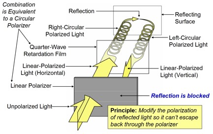
Figure 2: The use of a circular polarizer
to eliminate reflections from a surface.
(Artwork courtesy of Gunze USA)
In Figure
2 above, unpolarized light goes through a linear polarizer and becomes polarized
in the direction of the polarizeris axis (shown as horizontal in Figure 2).
The light then goes through a quarter-wave retardation film and becomes right-circular
polarized. (A retardation film's name comes from the fact that it "retards"
or delays the phase of light waves sent through it by a quarter-wavelength,
which changes the polarization of the light. The combination of a linear polarizer
and a retardation film creates a circular polarizer.) Circularly polarized
light changes orientation when it bounces off a surface, so the reflected
light on the right side of Figure 2 becomes left-circular polarized. When
the light goes back through the retardation film again, it reverts to linear
polarization, but this time at right angles to the original direction of polarization.
The linear polarizer therefore blocks the reflected light. In Figure 2 the
linear polarizer and retardation film are shown separately for clarity; in
actual practice they are laminated together.
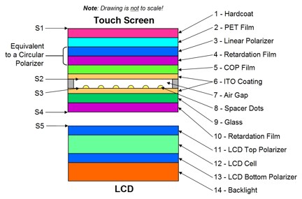
Figure 3:* The application of a circular
polarizer to a resistive touch screen.
Figure 3
above illustrates how a circular polarizer is applied to a resistive touch
screen to reduce reflections. Figure 3 is identical to Figure 1 with the addition
of items (3), (4) and (10), and a change in item (5). The circular polarizer
(items 3 & 4) is identical to the circular polarizer in Figure 2, except
that they are shown as laminated together. Item (5), the touch-screen flexible
membrane, can't be made of PET in a circular polarizer system because PET
introduces some undesirable retardation of its own. Instead, the membrane
must be made of a different, non-retarding material. One of the commonly used
materials is cyclo olefin polymer (COP) film, shown here as an example.
The second
retardation film (item 10 in Figure 3 above) is not involved in reducing reflections.
It is required because of the presence of the circular polarizer. The light
emitted by the LCD (from the backlight) is linearly polarized as a result
of items (11) and (13).* This light would normally be blocked by the circular
polarizer (3 & 4) the same way that reflected light is blocked. The second
retardation film changes the light emitted by the LCD from linearly polarized
to circular polarized so that it can go through the circular polarizer (items
3 & 4) and be seen by the user. Without item (10), all light from the
LCD would be blocked.
The circular
polarizer reduces the reflections from surfaces S2 and S3 to a very low level
(about 0.1% each). However, its effect starts at item 3 and ends at the top
surface of item 10. That means that surfaces S1, S4 and S5 still require expensive
AR coatings. The best performance that can be achieved with this scheme is
therefore a reflectivity of 1.7% (S1 through S5 = 0.5% + 0.1% + 0.1% + 0.5%
+ 0.5%). This is a lot better than 20% but still not quite good enough.
Assuming a backlight brightness of 500 nits, the ECR formula estimates a contrast
ratio of (1 + (500 / 170)) = 3.9, which is still only ibarely readable in
sunlight.
GD-Itronix'
Ultimate Solution: DynaVue
GD-Itronix
has taken two significant steps beyond the structure illustrated in Figure
3. The first step is to increase the backlight brightness moderately to 500
nits. This causes fewer problems than the 1,000 nit backlight described under
"High-Brightness Backlights" above.
The second
step is to relocate the top polarizer on the LCD (item 11 in Figure 3) and
the second retardation film (item 10 in Figure 3). This new construction is
shown in Figure 4 below, where the relocated LCD top polarizer is item (3)
and the relocated retardation film is item (10).
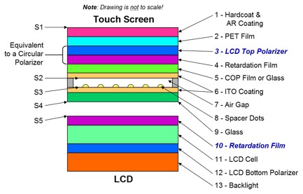
Figure 4: The construction of GD-Itronixi
DynaVue outdoor-readable touch-screen display.
The second
retardation film (item 10 in Figure 4) is still required because of the circular
polarizer (items 3 & 4), as explained under Figure 3. However, the new
location of the second retardation film means that reflected light from surfaces
S2 through S5 are all blocked by the circular polarizer. This means
that the only surface that requires AR coating in this construction is S1,
which makes it more economical. The performance that results from this construction
is a reflectivity of 0.9% (S1 through S5 = 0.5% + 0.1% + 0.1% + 0.1% + 0.1%).
Finally, this is a good number! Plugging a
500-nit backlight brightness and the 0.9% reflectivity into the ECR formula
yields the following result:
DynaVue
ECR = 1 + (500 / (10,000 x 0.009)) = 1 + (500 / 90) = 6.6:1
This is
well within the "adequately readable in sunlight" range of 5:1 to 9:1 shown
in the ECR table near the beginning of this article.
Just how
good is this? The notebook with the best outdoor readability on the
market today is a semi-rugged Dell notebook without
a touch screen). The Dell has a 500-nit backlight and an AR-coated cover-glass
optically bonded directly onto the LCD that produces a total reflectivity
of 0.5%. The ECR formula estimates the following result for the Dell:
Dell
ATG ECR = 1 (500 / (10,000 x 0.005)) = 11:1
From the
raw numbers, it sounds as though the Dell at 11:1 should be substantially
better than a DynaVue-equipped Itronix product at 6.6:1. However, someone
who has seen the Dell notebook and the new Itronix VR-2 DynaVue-equipped
notebook side-by-side outdoors in direct sunlight told the author that they
are very close in appearance. This is an amazing achievement
for a touch-screen-equipped notebook. Panasonic's best effort, the fully AR-coated,
1000-nit-backlight Toughbook 30 only achieves an estimated effective contrast
ratio of around 3.5:1. (This is based on an analysis of all available product
literature, not on actual measurements or on data from Panasonic.)
The Secret
Sauce
Comparing
Figures 3 and 4, the "secret sauce" clearly is the relocation of
the LCD's top polarizer and the second retardation film. This eliminates almost
all of the reflections from surfaces S4 and S5, which allows the total reflectivity
to be reduced to less than 1%. It also decreases the amount of light lost
in the touch screen, since there are only two polarizers in the system instead
of three. While the secret sauce sounds relatively simple, accomplishing it
is definitely not. It requires very close cooperation between the touch screen manufacturer, the LCD manufacturer and the computer manufacturer to pull off this kind of supply-chain magic.
A Few
Remaining Details
Readers
skilled in the art may notice that there's no anti-glare (AG) coating shown
in the DynaVue construction in Figure 4, only AR (item 1). GD-Itronix has
determined that an AG coating actually decreases DynaVue's performance.
GD-Itronix found that (a) the measured reflectivity of an AG-coated DynaVue
screen is slightly higher, and (b) users testing actual units unanimously
said that the image on an AG-coated screen was less sharp (due to diffusion
of the light emitted by the LCD).
Sharp-eyed
readers may also notice that item (5) in Figure 4, the touch-screen's flexible
membrane, is labeled as "COP Film or Glass." There is no
difference in reflectivity between the two materials, since there are no exposed
surfaces. However, using very thin flexible glass (0.1 mm) instead of COP
film provides a reliability advantage. The two primary causes of touch-screen
failure are (a) cosmetic damage to the top surface, and (b) cracked ITO coating
due to flexing. COP (or PET) film allows the ITO coating to flex at a smaller
radius than glass, which makes the touch-screen lifetime shorter. This is
why the typical specified lifetime of a 4-wire touch screen used with a stylus
is only 100,000 characters.
Readers
skilled in the art may also ask why optical bonding isn't considered in DynaVue's
construction, i.e., bonding the surfaces of items (9) and (10) in Figure 4
to eliminate reflecting surfaces S4 and S5. There are two reasons: first,
once bonded, the touch screen is very difficult to remove. This means that
when a touch screen must be replaced for cosmetic reasons, the LCD must also
be replaced -- which is uneconomical. Second, the performance gain by optically
bonding these two surfaces is only 0.2%, which is a small gain to trade off
against (a) the loss of touch-screen replaceability, and (b) the added cost
of the bonding. Just for the record, the 0.2% reduction in reflectivity would
increase the effective contrast ratio from 6.6:1 to 8.1:1, which is an improvement
of 23%.
Finally,
a few of the major LCD manufacturers such as Samsung are just beginning to
talk about the possibility of "integrated touch screens" in the
near future. What they're really talking about is what GD-Itronix has already
done.* By relocating the top polarizer on the LCD, they are effectively "integrating"
the touch screen into the LCD. All that's missing is optically bonding the
touch screen to the LCD, which as just noted, has some clear disadvantages.
The Bottom
Line
Outdoor
readability is all about contrast, not brightness. The objective is to get
the effective contrast ratio high enough so that the screen can be read comfortably
outdoors. Increasing the effective contrast ratio requires balancing two factors,
the amount of light reflected by the screen (reflectivity) and the amount
of light emitted by the screen (backlight brightness). Managing only one of
the factors won't produce optimum results.
This article
has described four levels of touch-screen treatment, ranging from none to
GD-Itronix' DynaVue, which the author believes is the best on the market today.
The table below summarizes the reflectivity data that has been presented in
this article (in the order it was discussed).
|
Touch-Screen
Treatment |
Surface
S1 |
Surface
S2 |
Surface
S3 |
Surface
S4 |
Surface
S5 |
Total
Reflectivity |
| Untreated |
4% |
5% |
5% |
4% |
2% |
20% |
| 5
AR coatings |
0.5% |
2.5% |
1.0% |
0.5% |
0.5% |
5% |
| Circular
polarizer |
0.5% |
0.1% |
0.1% |
0.5% |
0.5% |
1.7% |
| DynaVue |
0.5% |
0.1% |
0.1% |
0.1% |
0.1% |
0.9% |
This article has
also described a number of real and hypothetical products with and without
touch screens, and with varying combinations of reflectivity and backlight
brightness. These are summarized in the table below (in the order they were
mentioned).
|
Product
Configuration |
Touch
Screen |
Backlight
Brightness |
Total
Reflectivity |
Effective Contrast
Ratio (ECR) |
|
| Standard
notebook |
No |
200 nits |
2% |
2:1 |
|
| High-Bright
industrial display |
No |
1,000 nits |
2% |
6:1 |
|
| High-Bright
industrial display
with
untreated touch screen |
Yes |
1,000 nits |
20% |
1.5:1 |
|
| Notebook
with 5 AR coatings |
Yes |
500 nits |
5% |
2:1 |
|
| Notebook
with circular polarizer |
Yes |
500 nits |
1.7% |
3.9:1 |
|
| GD-Itronix
VR-2 touch-screen
notebook
with DynaVue |
Yes |
500 nits |
0.9% |
6.6:1 |
|
| Dell
notebook |
No |
500 nits |
0.5% |
11:1 |
|
| Panasonic
Toughbook 30 |
Yes |
1,000 nits |
4% |
3.5 |
|
| Optically
bonded DynaVue
(hypothetical,
not available) |
Yes |
500 nits |
0.7% |
8.1:1 |
|
The DynaVue display technology also meets DOD-STD-3009 military standard for cockpit displays for viewability and ambient light ratio.
Geoff Walker, Pen Computing's
Technology Editor, currently heads his own technical marketing consulting firm,
Walker Mobile, LLC.
Based in Silicon Valley, Geoff has particular expertise in touch screens &
digitizers, displays & enhancements, and mobile computers running Windows.
Geoff also writes for SID's Information Display
magazine and the Veritas
et Visus series of display-industry newsletters.* Geoff can be reached at
geoff@walkermobile.com or 1-408-945-1221.
|